

MIT | The Media Lab | NeCSys | The Network | Structure / Connectors / Hookups
Technically, a gateway is any device that is attached to more than one network segment, and passes data between the two (or more) different network segments. Gateways vary widely in their function, and are differentiated by the network layer they operate on.
ROUTERSRouters route data packets from one network to another at the Network and Transport layers. A Router looks at the IP headers of each packet, and, depending on the Source, Destination and Type of packet, sends it along to its destination, translates it, or filters it out of the network. The 4 main building Routers reside in the Master Distribution Frame in E15-040. Their names are Nexus, Plexus, Lexus and Taxus. These Routers form the central core of the Media Lab's Network; all data to and from hosts not on the same subsegment travels through one or more of the main building routers. |
 |
BRIDGESBridges transport data packets from one network to another at the Network layer. A Bridge decodes the IP headers of each packet, and sends it to another network if it finds the destination in its brdging table. The bridge tables are built automatically by observing which network each Source is on, and via the ARP protocol. Since Bridges do not offer the full range of filtering, protocol- translation, management and security features that routers do, we have replaced nearly every Bridged network segment in the Lab with a Routed segment. |
A switch is a particular implementation of a gateway. Many gateways have a single internal "backbone" bus that carries all of the traffic passing through that gateway; this bus can become saturated under heavy traffic.
A Switched Gateway attempts to bypass this bottleneck by allocating a private one-to-one connection between each Source and Destination. Since each connection is travelling on a separate path, each has access to the full bandwidth of that path, regardless of how much data is on other paths.
The main building switch at the Media Lab is a NORTEL / Fore ATM (Asynchronous Transfer Mode) Switch, running the OC3 protocol. Each fiber pair on the switch is capable of carrying 155 megabits/second.
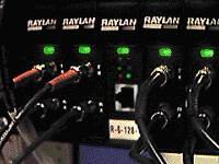
CONCENTRATORSConcentrators merge the connections from many computers onto a single network feed (or trunk connection). This feed may be a shared-access medium, such as Ethernet, or a single- or dual-attatch ring, such as FDDI. A concentrator differs from a repeater in that it usually offers some form of per-port status and control, for example, disabling ports which are currently non-operational. This is a Raylan model 1600 10baseFL Ethernet concentrator, the most popular concentrator at the Lab. Note the distinctive hot-swap Fiber Drop Cards, as well as the SNMP Management Card, which indicates the traffic and collision rates on this segment. The two FDCs to the left of the management card are Ring Connection cards. |
 |
A Repeater is a simple network device which amplifies the signals on shared-access medium, such as Thinnet Ethernet. A repeater allows one long wire to be broken up into several shorter wires, with the signals on each simply copied onto the other legs. A repeater ONLY deals with the signals at the physical/medium level--it performs no timing or framing changes.
Media Converters are devices which translate network connections from one media to another (Serving as a level-1 gateway). A Media Converter is used, for example, to connect a 10baseT-only network node to its fiber concentrator.
 The
Allied Telesis / CenterCom MR121T is a AUI-to-10baseT Media Converter,
suitable to attach a 10baseT-only node to our 10baseFL network with the
addition of a fiber tranceiver.
This unit is commonly used on some models of the DEC Alpha at the Lab. [50% of actual size]
These are our the most popular transceivers in use at the Media Lab . . .
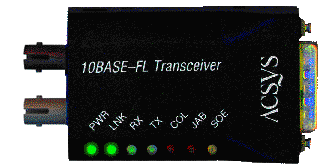
10baseFL tranceiver, ACSYS modelThis is the ACSYS/ Connectware 10baseFL tranceiver. It attaches to the AUI port (10base5) of a computer or network device. This model uses ST fiber connectors (10baseFL). |
(actual size) |
The ACSYS tranceiver has LEDs to indicate AUI power received, LINK (carrier signal being received), RX (Data being received), TX (Data being transmitted), COLLISIONS detected, and JABBER detected. In normal operation, POWER and LINK are solid green, RECEIVE flashes fairly often, TRANSMIT blinks, and COLLISION only blinks (RED) occasionally. Solid collisions means serious troble for the tranceiver's subnet. JABber and SQE LEDs should also be OFF.
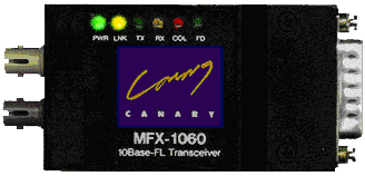
10baseFL tranceiver, Canary model MFX-1060Connects AUI (10base5) to Fiber Ethernet (10baseFL), using ST connectors. |
(actual size) |
This 10baseFL transceiver provides POWER, LINK, Transmit (TX), Receive (RX), COLLISION and Full Duplex (FD) indicators.
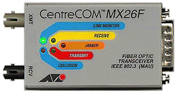
10baseFL transceiver, ATI MX26FConnects AUI (10base5) to Fiber Ethernet (10baseFL), using ST connectors. |
(actual size) |
The MX26F provides LINK, Transmit (TX), Receive (RX), COLLISION and JABBER indicators.
10baseFL transceiver, ATI MX80FConnects APPLE Ethernet (Apple-AUI, AAUI) to Fiber Ethernet (10baseFL), using ST connectors. |
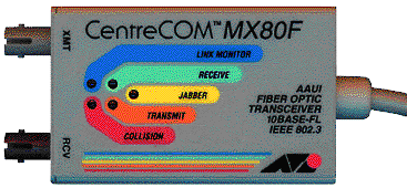
(actual size) |
The MX80F is an Apple-specific device. It attaches to the 'Built In Ethernet' port on Macintosh and Power PC models, and provides 10baseFL via fiber ST connectors. This model has LINK, Transmit (TX), Receive (RX), COLLISION and JABBER indicators.
10baseFL transceiver, Raylan modelThis is a Raylan-brand 10baseFL transceiver. It attaches to the AUI port (10base5) of a computer or network device and translates electrical signals into modulated light over fiber-optic cabling. This model uses ST fiber connectors (10baseFL), accessed through a cutout in the rear of the metal case. The Transmit (TX) connector is on the left with the connectors pointing up. Note: This model is being phased out of use. |

(FRONT, 50% of actual size) |
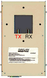
(REAR, 50% of actual size) |
The Raylan transceiver has a single bi-color LED:
GREEN = LINK OK, receiving carrier
ORANGE = NO LINK, no carrier (check fiber net connection)
NO LIGHT = No Power (check AUI cable and host connection).
MIT | The Media Lab | NeCSys | The Network | Structure / Connectors / Hookups
Comments or suggestions? Fill out a comment form.